Download STC Order Form and email or fax to us. Note: we need the information in our STC Order Form for our STC records

It’s also very important for the ignition timing to be correct. Even a slight advance will increase the CHT’s notably
After 18 years of experience, I realised it was cowl flap control that determined the T.B.O. of the cylinders and the fact that they are not foolproof and in some cases inadequate to provide sufficient cooling to enable engines to reach their T.B.O. without cylinder removal, especially in warmer climates.
If you do not believe me just go to your 182 and close the cowl flaps, then have a look at the total air outlet area. In my opinion and experience it is not anywhere near enough for the two hundred and thirty horse power engine.
From observing other engine installations that have their engines repeatedly run through to T.B.O. without any cylinder problems, we came up with a target operating CHT of 300° F (about mid green on an accurate standard Cessna CHT gauge).
We acknowledge that these engines will certainly run fine with CHT’s all the way up to the 460°F red line but have concluded that any operations with CHT’s above 350°F will come at a cost and that is premature cylinder related problems. We now advise T.C.M. powered 182 owners to give their engines plenty of cooling air using cowl flaps and to try not to exceed our target CHT reading of 300°F (mid green on the standard Cessna CHT gauge with a Bayonet type probe). Note – add 50°F to our noted temperatures if a spark plug type CHT probe is being used. With our target temperatures in mind, we were now starting to see vast improvements in cylinder T.B.O.
We also found that our customers had to fly with their cowl flaps wide open to achieve CHT readings of 300°F when the ambient temperature reaches 30°C. Above 30°C ambient temperatures, CHT readings of 300°F and below could not be maintained, and when the ambient temperature is around 40°C the CHT’s rise to approximately 450°F just short of the 460°F red line.
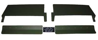
As we could not achieve our desired objective, which was to maintain the CHT readings around 300°F + or – 50°F and to make the cooling system fool proof we removed the cowl flaps and fitted fixed shortened type flaps with a trailing edge augmentor strip.
This made the cooling of the engine foolproof and lowered each cylinders CHT reading by 50 to 65°F with a medium amount of cooling drag.

The larger air outlet areas also make it a lot easier to carry out engine oil changes and remove the lower engine cowl induction air snorkel from the carby air box to facilitate lower engine cowl removal. It also eliminates the continued maintenance of the cowl flap hinges and control cables.
This modification without a doubt has certainly improved cylinder T.B.O. and has reduced the labour involved in engine oil changes and lower engine cowl removal. It is also easily reversible if the aircraft is relocated to an operating area where the ambient operating temperatures are very low (10°C and below).
H.A.S. S.T.C. No. ASA038ML (AU S.T.C only is available) applicable to all Cessna 210J, K, L, M, N, R, T210L, T210M, T210N and P210N aircraft.

Cessna 210 Oil Drain Valve Mod kit includes S.T.C., Engineering Order (paper work package) and drain valve with hose. Australian customers $AU500 + $25 Post & Packaging, plus GST. International customers $US400 + $AU70 Post & Packaging. (USD/AUD exchange rate used is the rate advertised by Westpac Bank)
Frequent engine oil changes certainly pay more dividends than one can initially imagine. Unlike automotive engines our aviation air-cooled piston engines have to run relatively large working clearances in the piston ring department, which leads to notably more piston/ring blow by.
By products of combustion are water (moisture) and acids which contaminate the engine’s oil and cause corrosion to form on internal components. Corrosion pitts are stress raisers which can cause cracks to develop and in some components such as impulse couplings, notable advanced wear is caused by the iron oxide (rusty) abrasive paste that forms on and wears out the paul pivots. The engine manufacturers have strict corrosion inspection criteria come engine overhaul time. Replacement gears, cam and crank shafts are very expensive and can significantly increase an engine overhaul bill.
Piston ring blow by also causes the oil to dilute by about 8 to 12% after approximately 30 hours of operation. This is why the consumption rate increases toward the 30 hour interval mark. The quality of lubrication also deteriorates in line with the increase in dilution.
If changing the engine oil in an engine can be made easy it is more likely that it will, and can, be done on time and even more regularly such as 4 monthly, 25 or 33 hour intervals.
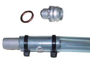
Our flush type oil drain valve installation modification uses a tested and proven oil drain valve and makes changing the engine oil in the later Cessna 210 series aircraft very easy (no more lockwiring, spilt oil or skin off the head parts when working through the nose gear door area).
Instead of reinstalling the oil drain plug you could install our drain valve modification and not have to go through that routine (drain plug removal and reinstallation) procedure again. Our drain hose assemble simply offers up into an installed drain valve and is held there with positive friction. The action of inserting the drain hose assembly opens the valve, which is spring loaded to the closed position. It is even easier to use than the more conventional type drain valves that need to have a hose attached to them first. This modification is a real time saver and promotes added safety and good maintenance practices which certainly assists in getting an engine to its manufacturers published T.B.O.
H.A.S. S.T.C. No. ASA039ML approved for Cessna models 206 and 210 series aircraft.
Cessna 206 aircraft eligibility 206, P206, P206A, P206B, P206C, P206E, U206, U206A,U206B, U206C, U206D, U206E, U206F, U206G, TU206A
Cessna 210 aircraft eligibility 210, 210A, 210B, 210D, 210E, 210F, 210G, 210H, 210J, 210K, 210L, 210M, 210N, 210R, T210G, T210L, T210M, T210N, P210N
H.A.S. US FAA S.T.C. No. SA01763WI approved for Cessna 206 models, aircraft eligibility as for AU S.T.C.
H.A.S. US FAA S.T.C. No. SA01744WI approved for Cessna 210 models, aircraft eligibility as for AU S.T.C.


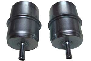
Continental Induction Drain Filter Mod kit includes filters, S.T.C. and Engineering Order (paper work package). Australian customers $AU250 + $25 Post & Packaging, plus GST. International customers $US250 + $AU50 Post & Packaging. (USD/AUD exchange rate used is the rate advertised by Westpac Bank)
Most of the TCM powered (IO-470, IO-520, TSIO-520 and field retro fitted IO-550 series) engines installed in Cessna single engine aircraft do not have a check valve in the engine induction drain lines to close them off after the engine is started. As a result these open ¼” (diameter) aluminium lines which are connected directly to the induction manifold (one each side) and are positioned to overboard excessive priming fuel at the inboard sides of the cowl flap openings, just forward of the fire wall, enable large amounts of grit/sand/dust or whatever to be sucked up through them into the engines induction system and cylinder assemblies. (Just ask anyone who works on these engines what they find on the inner walls of the induction pipes.)
The ingestion of grit/sand/dust causes notable cylinder and piston ring wear. We have found that installing our in line filters, eliminates the injection of grit/sand/dust through induction drain lines and significantly reduces cylinder and piston ring wear. It also reduces spark plug electrode breeching and is a positive step to assist in obtaining the manufacturer’s published engine T.B.O. and improves engine reliability and safety.
Our TCM Cessna 206 & 210 owners generally don´t add any oil between their 25 Hr or 4 monthly oil changes


